The final circuit is very small so that it can work as an emergency portable battery charger. Almost all USB powered devices (that can be charged via USB cable) like mobile phones, iPod, MP3 players, cameras etc. can be charged. It uses AA 1.5V batteries (even rechargeable batteries) and can be upgraded to higher capacities.
Portable Mobile Battery Charger with Over Voltage Protection
Circuit
Working
A portable mobile charger with over voltage protection is presented in this project. The circuit can be used to charge a mobile with the help of 4 AA batteries. As the components are discrete, an over voltage protection system is also included in the event of failure of any component. The working of the circuit is explained below.
The main component in the circuit is the IC 7805, which is a 5V voltage regulator that allows a maximum current of 1.5A. Hence, the mobile can be charged with a maximum current of 1.5A depending on the dry batteries used. The Zener diode ensures that the output voltage doesn’t exceed 5.6V and in case the output voltage exceed 5.6V, the Zener diode switches on the SCR and the input to 7805 is cut off. A 2A fuse can be used before IC 7805 to ensure that its input is cut off when over voltage condition occurs. The output of 7805 is connected to a female USB connector and from which a mobile can be charged. In the practical implementation, we used four 1.5V AA batteries that are rated 1.5A.
Output Video
Portable Mobile Phone Charger using Boost converter
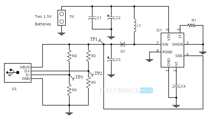
Circuit Diagram
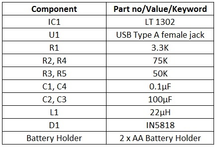
Circuit Components
Components Description of Battery charger circuit
LT 1302: It is a step-up DC/DC converter by Linear Technology. The input voltage can be as low as 2V and the output current can be up to 600mA. USB Type A female jack: It is an USB female jack of type A and fits on any PCB. A type A male to male (USB to microUSB) cable can be used to connect to external devices. IN5818: It is a Schottky Diode. As the application is of switching regulator type, normal diodes like IN4001 are not suitable. A Schottky diode have a high switching speed and very low forward voltage drop. L1 (10µH): It is an inductor. The main function of this inductor is to hold the current and release this current to the output capacitor. It should be able to handle a minimum current of 1A. C2 and C3 (220µF): These are power supply capacitors. They are electrolytic capacitors and are used for eliminating any AC ripples. C1 and C4 (0.1µF): These are bypass capacitors. C1 is used to stabilize the output and short any AC signal to ground (or filter/block unwanted noise signals).C4 is used to stabilize the internal reference voltage of the LT1302. AA Batteries: These are the source of power. 2 AA batteries of 1.5V each are connected in series so that the voltage is 3V. This is given as the input supply.
Working
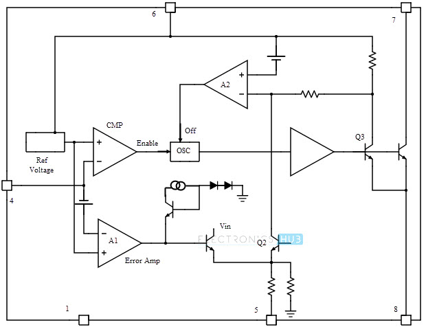
The heart of the battery charger circuit is LT1302, which is a step-up DC/DC converter. The minimum allowable input to LT1302 is 2V. This input is boosted to 5V at an output current of 600mA. We are using a 3V input (using two AA batteries). LT1302 operates in two modes: Burst mode and current mode. Burst mode operation is for lighter loads and current mode operation is for heavy loads. The voltage at pin 4 (which is the output voltage of the circuit that is fed back to pin 4) is internally compared with a reference voltage of 1.24V by a comparator. If this feedback voltage is less than the reference voltage, the internal oscillator is turned ON. The output of this oscillator will alternately turn ON and OFF the transistor. When Q4 is ON, there is a current built up in the inductor L1. When Q4 is OFF, the current flows into the output capacitor C3 via the diode. Because of the faster switching action, the diode used is a Schottky diode. As the output voltage increases, the voltage at the feedback pin (pin 4) also increases. Once the feedback voltage exceeds the reference voltage (plus some hysteresis of comparator), the oscillator is turned OFF by the comparator (as its output falls low). But in order to make LT1302 work in current mode even at light load, a resistor is connected between pin 5 and ground (3.3K resistor as shown in the circuit). In current mode (which is the case here), the comparator stays ON which in turn keeps the oscillator ON. Now the switch current is limited to 1A by A2, Q2 and Q3 and is regulated by the output of the error amplifier (A1). The output voltage will be around 4.9V. The internal circuit of LT1302 is shown below. (Particularly for geeks. Others can simply ignore this).
Circuit Description
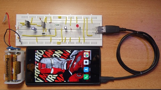
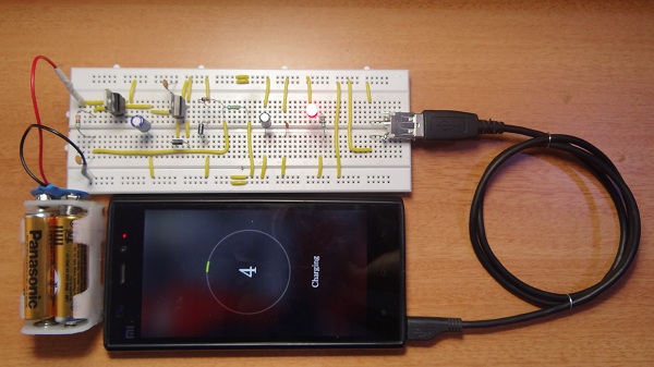
Connect the components as per the circuit diagram (preferably on a breadboard before assembling it on a PCB). There are three test points mentioned in the battery charger circuit (TP1, TP2 and TP3).The main circuit is until the output capacitor C3, where the output voltage should be taken. Test for the voltage at TP1 and this should be in the range of 4.8V<TP1<5.2V. If the voltage at TP1 is less than 3V, then remove the batteries and recheck all the connections. The circuitry after the output capacitor is to configure the USB jack. USB female jack has 4 connections viz. Vbus, GND, D+ and D-. Vbus and GND are the power rails. Vbus is connected to the output of the main circuit whose output is ≈ 5V. D+ and D- are the data rails. As the USB is used for charging, these should be connected to a voltage greater than 0V but less than the voltage at Vbus. Hence, a voltage divider network is formed with the help of resistors R2, R3 (for D+) and R4, R5 (for D-). Two test points (TP2 and TP3) are given at this voltage divider outputs. The voltages at these test points should be approximately equal to 2V. Alternative Components LT1302 is a DC/DC step-up converter. There are some other IC’s that are available in the market which perform a similar operation. Some of them are LT1073, LT1111, LT1173, LT130x, MAX751 and MAX756. “LT” IC’s are manufactured by Linear Technologies and “MAX” IC’s are manufactured by Maxim Integrated. (The circuit components and connections might vary according to the DC/DC IC used). IN5818 is a Schottky diode. There are some other Schottky diodes that can be used for the same purpose. They are MOTOROLA MBRS130LT3 and IN5817.
General Guidelines
Just plug-in the devices’ USB cable to the female USB jack in the circuit. That’s it. 5V Alkaline or Lithium AA batteries as well as rechargeable NiMH batteries are compatible. For the purpose of the efficiency of the circuit, it is advised to keep the input voltage less than or equal to 4.5V (but definitely more than 2V). In case of higher input voltages (> 4.5V), the above mentioned circuit isn’t compatible as some modifications are to be made. The amount of charge this circuit can deliver will depend on two factors: AA battery capacity and device battery capacity (do not expect a full charge even with completely charged AA batteries as today’s device batteries have more capacity i.e. more mAh).
thank you 🙂 Thanks Comment * Name * Email * Website
Δ





![]()