An electric conductor or a circuit element with the property of Inductance is called as Inductor. When there is a change of current in a coil or a twisted wire (inductor), it opposes this change by generating or inducing an electromotive force (EMF) in itself and nearby conducting materials. Capacitance is the measure of the ability of a conductor to store electric charge i.e. electric field energy. In contrast, Inductance of an electrical conductor is the measure of its ability to store magnetic charge i.e. magnetic field energy. An inductor stores the energy in the form of magnetic field. As magnetic field is associated with flow of current, inductance is associated with current carrying material. The inductance of a coil is proportional to the number of turns of the coil. Di-electric materials like plastic, wood and glass have least inductance. But the Ferro magnetic substances (iron, Alnico, chromium ferroxide) will have high inductance.
The unit for inductance is Henry, micro Henry, milli Henry etc. It can also be measured in Weber/ ampere. The relation between Weber and Henry is, 1H = 1 Wb/A. To understand the inductance of a coil, we should know about Lenz law, which explains us how the emf will induce in an inductor. Lenz’s law states that “ The polarity of induced EMF due to change in the magnetic flux is such that, a current is generated whose magnetic field opposes the change in the flux which produces it”. Another definition of Inductance is “The electromagnetic force produced in a coil by applying the voltage of 1 volt, and is exactly equal to one Henry or 1 ampere/ second”. In other words, for 1 volt of voltage VL and the rate of flow of current is 1 amp/ sec then the inductance of the coil is L, measuring 1 Henry. This can be given as di/dt ( A/s) Where di is change in current, measured in Amperes dt represents the time (in seconds) taken for current to change. The induced voltage in the inductor (coil) is given as VL = -L di/dt (volts) The negative sign indicates the opposing voltage in the coil per unit time (di /dt). The inductance in a coil is of 2 types, they are
Self inductance Mutual inductance
Self Inductance
Inductance or self inductance is the property of a current carrying conductor where an EMF is induced in it when there is a change in flow of current. When an alternating varying current flows through the inductor coil, the magnetic flux in the coil will also vary, to produce the induced emf. This process is called “Self induction” and the inductance achieved by the coil is called “Self-inductance”. The concept of self inductance can be understood by assuming a current carrying circuit element or an inductor coil of N turns. When current flows through the coil, a magnetic field is produced in and out of the coil. There is a magnetic flux introduced because of this magnetic field. Then, the self inductance of the coil is the magnetic flux linkage per unit current. When the inductor coil intercepts the magnetic flux lines caused by an electric field, the self emf will be induced in the coil itself. In other words, the self-inductance means, the ability of a coil to oppose the current’s change. It is measured in Henry. The magnetic properties or the magnetic nature of a coil affects the self-inductance of the coil. This is the reason why Ferromagnetic materials are used to increase the inductance of the coil, by increasing the magnetic flux in it. The expression to find the Self-inductance of a coil, is L = N Φ /I Where N represents the number of turns in the coil Φ is the magnetic flux I is the current due to the produced emf L means the inductance value in Henries.
Self Induced EMF and Coefficient of Self Inductance
We know that the current flowing through the inductor is represented by I and Φ is the magnetic flux. They both are directly proportional to each other. So it can be represented as I ∝ Φ. The number of turns in the inductor is also proportional to the current in the coil. We can derive the relation between current and the emf induced in it as (dΦ )/dt = L (di )/dt The value of inductance depends on the geometry or shape of the coil. That is value is called “coefficient of self-inductance”. e = – (dΦ )/dt e = – L (di )/dt We can design the inductor coils as per our need by using the high or low permeability materials and using coils having different number of turns. The magnetic flux produced inside of a inductor core is given as Φ = B x A Here B is the flux density and A is the area occupied by the coil.
Self-inductance in a long solenoid
If we consider a long hollow solenoid having its cross sectional area A and length l with n number of turns, then its magnetic field due to the flow of current I is given as B = μ0 H = μ0(N.I )/l The total flux in the solenoid is given as N Φ = LI. Substituting this in the above equation, L = N Φ /I L = (μ0 N2 A )/ l Where L is self-inductance in Henry μ0 is the permeability of air or hollow space N represents the number of turns in the coil i.e. inductor A is the inner cross sectional area of the solenoid l is the length of the coil in meters. This is the self-inductance of the long length hollow solenoid. μ represents the absolute permeability of the material with which the solenoid is filled. Here in this case, we calculated the self-inductance for the hollow solenoid, hence we use μ0. To have the high permeability or to produce high magnetic flux we fill the solenoid with ferromagnetic substances like soft iron.
Self Inductance of a circular coil
Let’s find the self-inductance of a circular shaped inductor. Consider a circular coil with the area of cross section A = π r2, with N number of turns in it. Then the magnetic flux is given as B = μ0 (N.I )/2r The total flux in the circular conductor is given as N Φ = LI. Substituting this in the above equation, L = N Φ /I L = (μ_0 N2 A )/2r We know the area of circle is A = π r2, so self-inductance of a circular inductor is also given as L = (μ0 N2 π r )/2
Factors Affecting the Self Inductance
Observing the above equation of inductance, we can say there are 4 factors that affect the self-inductance of a coil, they are
Number of turns
The inductance of the coil will depend up on the number of turns of the coil. Number of turns or twists in a coil and the inductance are in proportional to each other. N ∝ L Higher the number of turns means grater the value of inductance. Lower the number of turns means lower the value of inductance.
Cross sectional area
The inductance of a coil will increase with increase in the cross sectional area of the inductor. L∝ N. If the area of the coil is high, it will produce more number of magnetic flux lines, this results in formation of more magnetic flux. Hence the, inductance will be high.
Coil length
The magnetic flux induced in a longer coil is less than that of the flux induced in short coil. As the induced magnetic flux reduces, the inductance of the coil also decreases. So the induction of the coil is inversely proportional to inductance of the coil. L∝ 1/l
Material of the coil
The permeability of the material with which the coil is wrapped, will have an effect on the induced emf and inductance. The materials with high permeability can produce low inductance. L∝μ0. We know μ = μ0 μr So L∝ 1 / μr
Self-inductance example
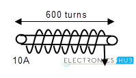
Consider a hollow core (inductor) having 600 turns of copper wire in it, which produces the magnetic flux of 10 milli Wb when we pass a DC current of 10 amps. Now let’s calculate the self-inductance of the copper coil.
To find the inductance of the coil, we use the relation between L and I. L = (N Φ)/I Given that, N = 600 turns Φ = 10 mille Weber = 0.001 Wb. I = 10 amps So inductance L = (600 x 0.01) / 10 = 600 Milli Henry
Mutual Inductance
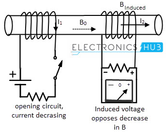
The phenomenon of inducing an emf in a coil as a result of change in current flow of its coupled or adjacent coil is called “Mutual induction”. Here, the two coils are in the influence of same magnetic field. As we discussed in the self-inductance concept, the emf produced due to mutual inductance can be explained by Faraday’s law and the direction of the emf can be described by Lenz’s law. The direction of the emf is always opposite to the change in the magnetic field. The emf induced in the second coil is due to the change in the current of the first coil. The emf induced in the second coil can be given as EMF2 = – N2 A ΔB/Δt = -M (ΔI1)/Δt Where M is the mutual inductance, which is the proportionality between the generated emf in the second coil and the current change in the first coil.
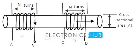
To understand the concept of mutual inductance, observe the above picture. In that we connect two inductors are wound around a single conductor. Let’s say them as loop 1 and loop 2. If the current in the loop 1 is varying then magnetic flux is induced. When the loop 2 intercepts the magnetic flux then without any current flowing directly into the second coil, there will be some emf induced. That is called Mutual inductance and this phenomenon is called “Mutual induction”.
Mutually Induced EMF and Coefficient of Mutual Inductance
Whenever we keep the 2 coils in the current varying field, there will be an emf induced because of the current flow. As the current in the loop varies, the magnetic flux also varies. In this case the mutual induction is a vector quantity because it may induce in 2nd coil due to the current flow in 1st coil, or may be induced in the 1st coil due to the magnetic flux (B) produced by the 2nd coil
When the current flowing in the inductor 1 varies, magnetic flux will be generated around it (according to Lenz’s law and Faraday’s law). Then, the mutually induced emf in the second coil due to current in 1st coil will be given as M12 = (N2 Φ12)/I1 Where M12 is the mutual inductance in coil 2 N is the number of turns in loop Φ12 is the magnetic flux generated in the coil 2 I1 is the current in loop 1 In the same manner, when we vary the current flow in inductor 1, magnetic flux will generate around it. Then the mutually induced emf in the 1st coil due to current in 2nd coil will be given as M21 = ( N2 Φ21)/I2 Where M21 is the mutual inductance in coil 1 N is the number of turns in loop Φ21 is the magnetic flux generated in the coil 1 I2 is the current in loop 2 The important thing we need to remember is M21 = M12 = M, irrespective of relative position of the two coils, size and the number of turns in them. This is called the ‘Coefficient of mutual inductance’. The formula for self-inductance of each coil is L1 = (μ 0 μ r N12 A)/l and L2 = (μ 0 μr N22 A)/l From the above equations, we can write M2 = L1 L2. This is the relation between self inductances of each coil and the mutual inductance. It can also be written as M = √(L1 L2 ) Henry. The above equation represents the ideal condition that there is no leakage of flux. But in reality, there is always some flux leakage due to the position and geometry of the coil.
Magnetic Coupling Coefficient or Coefficient of Coupling
The amount of inductive coupling between two coils is denoted by ‘Coefficient of coupling’. The value of the coefficient of coupling will be less than 1 and always greater than 0 i.e. it lies between 0 and 1. This is represented with ‘k’.
Derivation of coupling coefficient
Consider two inductor coils of length L1 and L2 having N1 and N2 turns respectively. The currents in coils 1 and 2 are I1 and I2. Assume that the flux produced in the second coil due to current flow I1 is Φ21. Then the mutual inductance will be given as M = N1 Φ21/ I1 Φ21 can be described as the part of flux Φ1 linked with 2nd coil. I.e. Φ21 = k1 Φ1 … M = N1 ( k1 Φ1) / i1 . . . . . . . . . . (1) Similarly, the flux produced in the first coil due to current flow I2 is Φ12. Then the mutual inductance will be given as M = N2 Φ12/ I2 Φ21 can be described as the part of flux Φ1 linked with 2nd coil. I.e. Φ12 = k2 Φ2 … M = N2 ( k2 Φ2) / i2 . . . . . . . . . . (2) Multiplying the equations (1) and (2), we get M2 = k1 k2 [N(1 Φ1 )/I_1 ]. [N(2 Φ2 )/I2 ] Now we know that the self-inductance of coil 1 is L1 = N1 Φ1 / i1 Self-inductance of coil 1 is L2 = N2 Φ2 / i2 Substituting L1 and L2 in the above equation we get M2 = (k1 k2) x (L1 L2) … M = √(k1 k2) x √(L1 L2) Let k = √ (k1k2) …M = k √(L1L2) Where k is the coefficient of coupling K = M/((√(L1 L2 )) ) We can describe the magnetic coupling of two coils by using the magnetic coupling coefficient. When the magnetic flux of one coil is completely links with the other, then the coefficient of coupling will be high. The maximum range of the coupling coefficient is 1, while the minimum is 0. When the value of coupling coefficient is 1, then the coils are called “Perfectly coupled coils”. If the value is 0, the coils are called “Loosely coupled coils”.
Note
K value will never be negative or never be a fractional value. Coupling coefficient of iron core coupled circuit is k = 0.99 Coupling coefficient of iron core coupled circuit is k = 0.4 to 0.7
Summary of self-inductance and Mutual inductance
‘Inductance’ is a phenomenon that a twisted coil experiences a magnetic force on it when it is applied with an electric voltage. An inductor stores the energy in the form of magnetic field. It is measured in Henry. The induction in an inductor can be explained by Lenz’s law and Faraday’s law. Lenz’s law states that “The induced EMF is generated in the current direction opposes the flux caused to produce that emf”. The inductance in a coil is of 2 types, they are
Definition of self-inductance: The self inductance of a coil is the induction of electromotive force in the soil when it is placed in a current varying circuit. This phenomenon of self-inductance is called “Self-induction”. Represented by L. L = N Φ /I Self-inductance of a long solenoid is L = (μ0 N2 A )/l Self-inductance of a circular core is L = (μ0 N2Πr )/2 Self-inductance will depend on 4 factors Number of turns in the coil (N), Area of the inductor coil (A), Length of the coil (l), Material of the coil. Definition of mutual induction: The phenomenon of inducing the emf in a coil as a result of change in current flow of its coupled coil is called “Mutual inductance”. M = √(L1 L2 ) Definition of coupling factor: The amount of inductive coupling between two coils is denoted by ‘Coefficient of coupling’. The value of coefficient of coupling will be less than 1 and always greater than 0. This is represented with ‘k’. K = M/((√(L1 L2 )) )
Vin=230Vav F=50Hz please suggest some of the formulas reqired to calculate the above inductor Comment * Name * Email * Website
Δ


![]()