Introduction
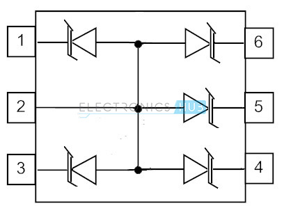
Today the markets of digital communication signal processing equipment and other portable devices has the need of developing a large number of small size electronic components. The integration of multiple functions and miniaturization of electronic components on the boards due to constraints on the board space provides the requirement of other packaging technologies. Signal diodes are used in switching operations, snubbing circuits on which short duration waveforms are concentrated, high speed data lines and other I/O parallel connected ports. These signal diodes have enormous applications in signal processing and digital communications. There is a series of signal diodes available in the market. Of them, 1N4148 series signal diode is widely used in a large number of electronic circuits due to its small size, power requirements and other useful parameters. In the following diagram pin 5 is used for ground. To combat the over space requirement on digital circuit boards, signal diodes are connected in parallel configuration forming an array called as small signal diode arrays. They are enclosed in a plastic case or glass case in single line or dual line packages, features from 4 to 14 diodes to provide common cathode or common anode configurations.
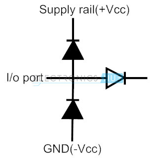
The space saving signal diode array configurations provide electro static discharge protection, heat control and over voltage transients. These advantages make the diode arrays, ideal to be placed in the circuits on PCBs. When the signal diodes are connected in series with the respective power supply terminals, then the data lines that are connected at the junction between the two signal diodes are protected from unnecessary transients and thereby the data will continue to pass along the data lines. If the signal diodes are connected in 6-fold, then the array can guard all the 6 data signal lines in a single inline package. Signal diode arrays can be used for regulating the voltage that is applied to circuit on the PCBs. If the voltage applied exceeds the maximum voltage rating, then the excess energy provided will be penetrated as heat which may damage the device.
BACK TO TOP
Signal Diode Arrays – In Series
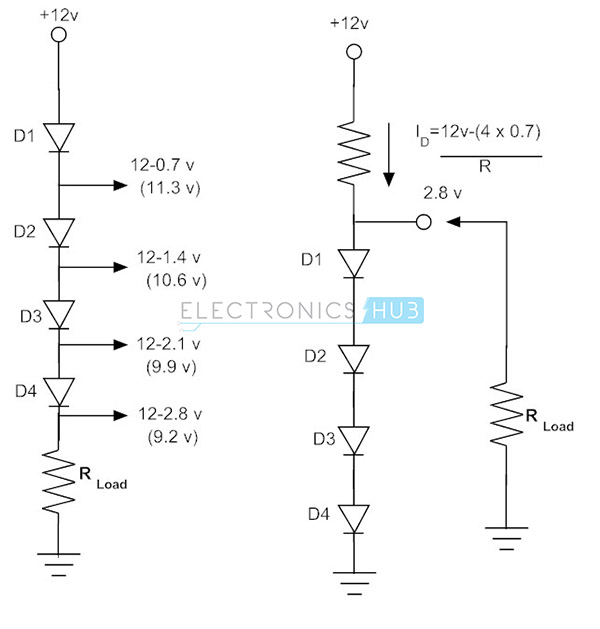
In order to protect the board from excess voltages the signal diodes can be connected either in series or in parallel configurations for providing the fixed known voltage within the limit. When the signal diodes are connected in series the maximum current required by the diodes in the array is same and the maximum voltage drop in the array will be the sum of all the forward voltage drops in the array of signal diodes. In the array of signal diodes in series configuration, the output voltage will be constant in spite of variations in the current in the load connected or in the variations of the input voltage applied. Hence supply of constant voltage is provided by the signal diode series combination. Since the forward voltage drop of silicon diode is 0.7 V and the current through the silicon diode alters by a fairly large number, the signal diode connected in forward bias will make a circuit of the simple voltage regulator. The individual forward voltage drop of each signal diode in series combination is thus subtracted from the input voltage applied to depart a certain amount of voltage across the load resistor connected at the end of the circuit. This is due to ON resistance of each diode in addition to the load resistance R. With the addition of a number of signal diodes in series, a large amount of declination in voltage will takes place. Furthermore the signal diodes connected in series, in parallel with the load resistor R act as a voltage regulator circuit.
BACK TO TOP
Freewheel Diodes
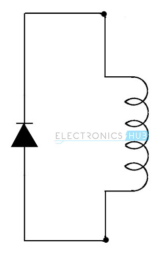
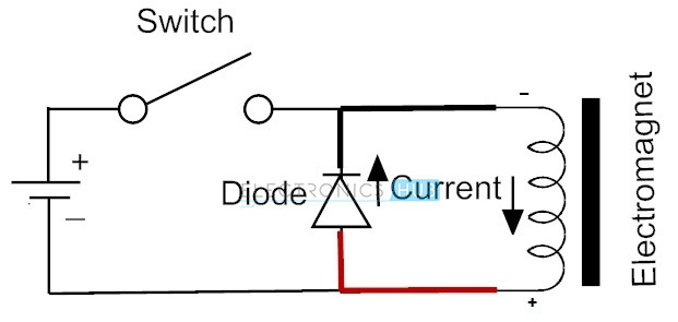
Freewheel diodes also termed as fly back diodes, suppression diodes or clamp diodes. Free wheel diodes or suppressor diodes are a combination of small signal diodes that are connected in the parallel combination across the inductive load to suppress the sudden voltage spikes when either of the supply voltage or connected inductive load is turned off, thereby freewheel diodes prevents the switching circuit from damage. These types of diodes provide the smooth current to the load connected, thereby eliminating the negative voltage at the load. It is mostly seen in rectifiers and probably useful in power electronics. One universal example of freewheel diode is 1N4007.
BACK TO TOP
Principle of Working
Whenever a voltage source is connected to a switch and an inductor load, then there will be a possibility of two steady states. In the first case when the switch is closed, the inductor connected at the end acting as a load will get the full energy from the input voltage applied and thus all the current in the circuit will pass from the positive terminal to negative terminal through the inductor. In the second case when the switch is opened, the inductor load experiences a sudden drop in the current and will defend against it with its accumulated magnetic field energy. When a positive potential is applied there will be a large negative potential concentrated and when a negative potential is applied there will be a large positive potential concentrated. Since no physical connection is made for passing the current, the charge carriers will cross over the band gap of the switch or transistor.
A freewheel diode prevents the crossover problem of the charge carriers with inductor load by allowing the inductor to draw current till the energy is penetrated through the diode and wire in a continuous loop. The freewheel diode acts as a forward biased diode with respect to inductor when the switch is opened, allowing the inductor to conduct electric current from the positive terminal to negative terminal in a continuous manner. The voltage present at the inductor load will be a certain function of the forward voltage drop of the freewheel diode and the total power dissipation time of the diode will be usually few milliseconds. BACK TO TOP
Selection of Freewheeling Diodes
Depending on the application required one would choose an ideal freewheel diode based on the parameters like maximum forward current capacity, least forward voltage drop and appropriate reverse breakdown voltage that are best suited for voltage at the inductor. Schottky diodes are best preferred in free wheel diode applications in switching converters. The prevailing series diodes 1N4001, 1M5400 are best used for dissipating the energy in the inductive load. BACK TO TOP
Freewheel Diode Applications
Free wheel diodes are used for switching applications when the inductive loads are switched off in relay driving circuits, H-bridge motor driving circuits. In the past years, the functioning speed of the many semiconductor switching type devices, either the transistor or any FETs have been reduced by the addition of a freewheel diode at the inductive load instead of using Schottky, Zener and other types of diodes in certain applications. But in the recent years, free wheel diodes are used most frequently due to their improved fast reverse-recovery times and the use of ultra fast semiconductor materials capable of operating at higher switching frequencies. BACK TO TOP PREVIOUS – SIGNAL DIODE NEXT – ZENER DIODE Comment * Name * Email * Website
Δ




![]()