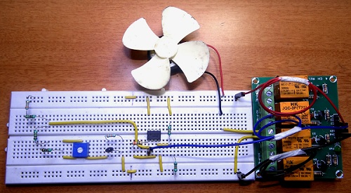
HVAC systems are responsible for thermal comfort as well as air flow and quality in vehicles as well as indoors. All the modern homes, offices and industries are equipped with HVAC systems and approximately 30-40 % of the power consumption in medium to large office buildings goes for heating and/or cooling systems. HVAC Thermostats are commonly used in residential and industrial buildings to control the temperature by switching on and off the heating and cooling systems. Thermostats often use a sensor like Thermistor to measure the temperature. A Thermistor is a temperature sensitive resistor where its resistance changes according to its surrounding temperature. In this project, we developed a simple thermistor based thermostat to control the heating or cooling system (depending on what part of the World you live in or your requirements). We designed the circuit using simple components like operational amplifier, thermistor and a relay. The circuit and working are explained in the following sections.
Circuit Diagram
Components Required
LM358 – 1 2N2222 – 1 20 KΩ Thermistor – 1 3.3 MΩ – 1 43 KΩ – 1 33 KΩ – 1 24 KΩ – 1 22 KΩ – 2 10 KΩ – 1 5.6 KΩ – 1 10 KΩ POT – 1 1N5919 5.6V Zener – 1 1N4003 – 1 12V Relay – 1
Circuit Description
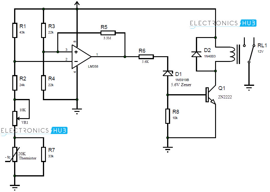
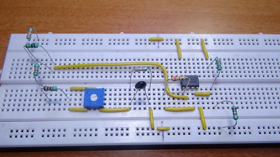
LM358 is the op amp IC used as a comparator in the circuit. It is applied with hysteresis by implementing positive feedback. The non-inverting terminal is given to the output of the voltage divider formed by R3 and R4. Another voltage divider is formed by resistors R1, R2, VR1, Thermistor and R7 and its output is given to inverting terminal of the amplifier. A positive feedback is given via R5 to the non-inverting terminal of the comparator. The output of the comparator is given to the NPN transistor through a Zener diode. The collector terminal of the transistor is connected to one end of the relay coil while the other end of the coil is connected to supply. The contacts of the relay can be connected to a heater or a cooler depending on the requirement and is not shown in the circuit.
Working
Thermostats are very important temperature sensing components that are part of many devices and systems like HVAC, central cooling or heating, air conditioning, refrigerators and even in medical applications like incubators. We have designed a simple thermistor based thermostat with a temperature range of 5 0C to 300C. This system is suitable for temperature control of a room as the tolerance of the system is around 30C. Thermistor is the main temperature sensor in the circuit. The resistance of the thermistor is dependent on the immediate surrounding temperature. There are two types of thermistors: PTC and NTC. In PTC or positive temperature coefficient type thermistor, the resistance increases with increase in temperature and decreases with decrease in temperature. In case of NTC or negative temperature coefficient type thermistor, the resistance increases with drop in temperature and decreases with rise in temperature. Generally, NTC type thermistors are used in thermostats. In this project, we used two 10 KΩ thermistors with NTC. A 10 KΩ thermistor has a resistance of 10 KΩ at 250C. If there is a drop in temperature, for example to 200C, the resistance goes up to 12.5 KΩ. If the temperature rises to 300C, the resistance falls to 8 KΩ. Keeping this in mind, the working of the simple thermostat is explained below. The positive terminal or the non-inverting terminal of the comparator senses the reference voltage. The room temperature is sensed by the negative or the inverting terminal of the comparator with the help of thermistor and some resistors. When there is a drop in the room temperature, the resistance of the thermistor increases and the output of the comparator will be low. This in turn will cause the relay to turn off and the load will conduct or stop conducting depending on the connection. The sensitivity of the circuit can be calibrated with the help of the variable resistor. A 10 KΩ trimmer is used for setting resistance according to on and off of the relay. Additionally, instead of using a single variable resistor, two variable resistors of 5 KΩ can be connected in series for better calibration.
Applications
Thermostats are used in many temperature control systems. The thermostat designed here can be used to control the temperature of a single large room. By using an LCD display and some additional components, live readings can be displayed for convenience. Depending on the application like room temperature control or refrigerator or heating system etc. the load can be connected.
Note
Depending on the load used like a heater or air conditioning system, the current and voltage rating of the relay must be checked. The thermistor must be placed at a place where the temperature is 250C while calibrating.
Comment * Name * Email * Website
Δ


![]()