The range of RF communication is very high when compared to IR communication. In this project, a wireless transmitter and receiver system using RF modules (RF Transmitter and RF Receiver) is implemented.
An RF Transmitter and Receiver pair is used for wireless communication. The wireless data transmission is done using 433 MHz Radio Frequency signals that are modulated using Amplitude Shift Keying (ASK) Modulation technique. In order to implement the wireless transmitter and receiver, we use an encoder IC HT12E and a decoder IC HT12D.
Circuit Diagram
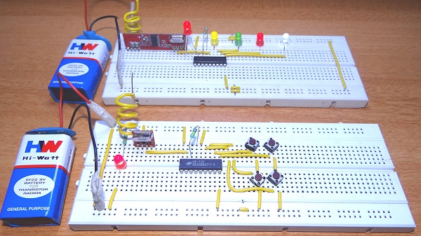
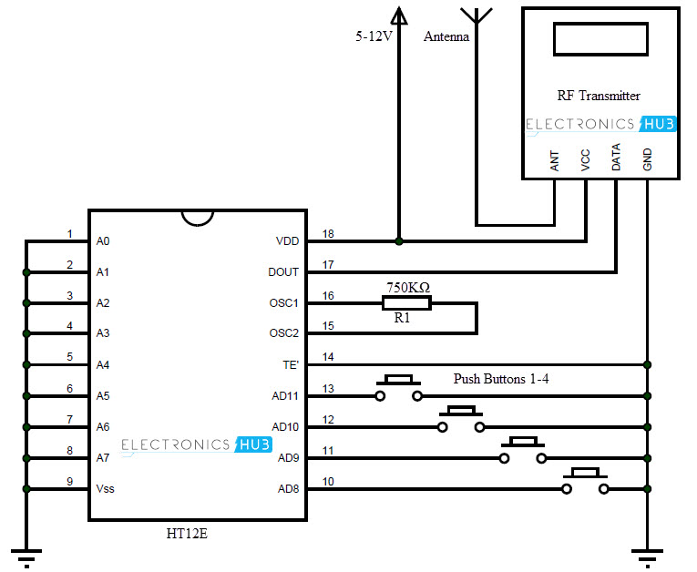
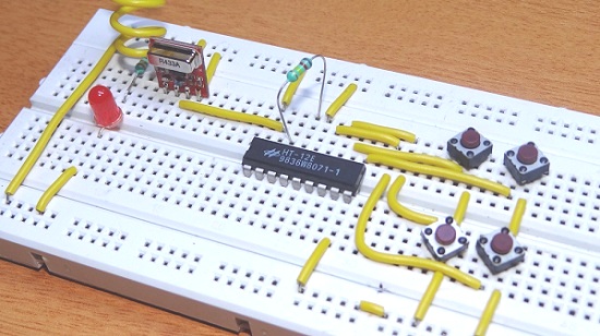
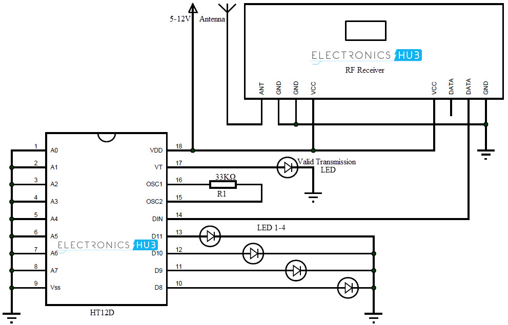
The circuit is divided into transmitter and receiver sections. The transmitter section consists of an RF Transmitter, HT12E encoder IC and four push buttons. The receiver section consists of RF Receiver, HT12D Decoder IC and four LEDs. An extra LED is connected to VT (Valid Transmission) pin of the decoder IC. This is used to indicate a successful transmission of data. A 750 KΩ resistor is connected between the oscillator terminals of encoder IC. This is to enable the oscillator. Similarly, a 33 KΩ resistor is connected between the oscillator pins of decoder IC.
Output
Transmitter
Receiver
Component Description
RF Transmitter and Receiver Modules: The wireless communication between transmitter and receiver sections is achieved using RF modules. A 433 MHz transmitter and receiver pair are used in this project. HT12E It is an encoder IC that converts the 4-bit parallel data from the 4 data pins into serial data in order to transmit over RF link using transmitter. HT12D It is a decoder IC that converts the serial data received by the RF Receiver into 4-bit parallel data and drives the LEDs accordingly.
Working
The aim of this project is to implement a wireless transmitter and receiver using RF modules. It uses radio signals to transmit the data. The working of the project is as follows. The transmitter and receiver sections are placed at a distance of at least 20 meters. In order to show the working of wireless communication between transmitter and receiver, 4 LEDs at receiver side are controlled by 4 buttons at transmitter section. The HT12E encoder IC converts the 4-bit data from the 4 data pins that are connected to buttons into serial data. This serial data is sent to RF transmitter. The RF transmitter transmits this serial data using radio signals. At the receiver side, the RF receiver receives the serial data. This serial data is sent to HT12D decoder IC which converts into 4 bit parallel data. The 4 data pins of decoder are connected to LEDs. According to the buttons pushed, the LEDs can be turned ON or OFF.
Applications
As RF Modules doesn’t require line of sight communication, the transmitter and receiver can be isolated over a distance and data can be transmitted successfully. The wireless transmitter and receiver can be used in car door and garage door controllers. They can also be used in home automation systems.
I have a Wireless RF transmitter and receiver 433 MHZ – RXB6 Module and a RasberryPi2. I want to create a Wireless Button for WebCam to take pics, the webcam is connected to a RasberryPi 2. My question is: Do I need to have the HT12D chip? Please reply as early as possible thanks can i use this design for ground penetration application? if i send signal from RF transmitter to ground , it should a reflect signal will be produced depending on ground layers and receiver will catch it ? is it possible? thanks alot Comment * Name * Email * Website
Δ


![]()